VRx Backpack Setup

Flashing Methods for Backpack Device:
Before wiring up your VRX Backpack into your VRX Module, you MUST first flash the VRX Backpack firmware, either via WiFi or UART/FTDI.
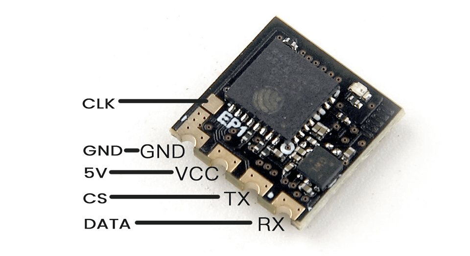
Good VRX Backpack candidates are the EP1 or EP2 receivers from Happymodel as these have Boot pads instead of Boot buttons. The Boot pad will be repurposed for the SPI Clock signal from the VRX module.
The VRX firmware you will flash into your Backpack Device will depend on what VRX module you want to connect it to. If you do not flash the correct firmware, it will not work properly.
Flashing via WiFi (ESP-based ExpressLRS Receivers)
Power up your selected VRX Backpack device (connect 5v and GND pads to any 5v power source). Let it go into WiFi Update mode (fast blinking LED) and load up the WiFi Update page. In the Address bar of your browser, add ?force=true to ensure it will accept the VRX Backpack firmware. The resulting URL should read http://10.0.0.1/?force=true (if you connected via Access Point) or http://elrs_rx.local/?force=true (if your device has connected to your local WiFi network).
Note
The ?force=true is not needed for ESP-based receivers with factory firmware. It is only required if you have previously flashed the receiver and want to repurpose it as a VRX Backpack.
Go to the Assets section of the Backpack Release on GitHub, Download the binary suited for your VRX module. Upload this binary into the VRX device using the Web Update page. Wait (~30s) until the LED on the VRX device has turned on again.
Alternatively, you can use the ExpressLRS Configurator to create your binaries for you. Build your binary, with the set binding phrase (Optional) as well as Home Network SSID and Password (Optional; available starting 0.2.0). Upload the resulting binary on the WiFi Update page as outlined above.
Flashing via UART/FTDI
Note
This method is best used for the DIY ESP01F VRX Backpacks, as these devices do not have any firmware from the factory.
Connect your FTDI RX pin into the TX pad of your VRX Device, and the FTDI TX pin into the RX pad of the VRX Device; then the 5V and GND pads. The Boot pad needs to be bridged with the Ground pad. Connect your FTDI, with the connected VRX device, into a free USB port (VRX Device's LED should light up SOLID). Using the ExpressLRS Configurator, select your VRX module, select the via UART method and set your binding phrase (Optional) and the Home Network SSID and Password (Optional; Available starting 0.2.0). Click Build and Flash and the compiling and flashing should commence. If done right, the Success bar should appear and your VRX Backpack should now be ready for wiring into your selected VRX Module.
Flashing TBS Fusion for the First Time
You will need an FTDI dongle (USB to UART Bridge) to flash the VRX Backpack firmware into your TBS Fusion module for the first time. You will also have to follow the TBS Fusion WiFi Module Unbricking Guide but instead of uploading the WiFi Firmware file from TBS, you will upload the VRX Backpack Firmware that the ExpressLRS Configurator compiled from Build.
Any subsequent firmware updates can be done via WiFi.
Starting with 0.2.0, you can also Update via your Home WiFi
With your Home Network SSID and Password set, when you activate the WiFi mode via the Lua script (WiFi Connectivity -> Enabled VRX WiFi), the Backpack will try to connect to your Home WiFi Network. Once connected, you can access the Web Update page via http://elrs_vrx.local/ and upload your firmware there.
The ExpressLRS Configurator will also detect the device after it has been connected. It will be listed in the "Device List" section, and you can press SELECT, so that the correct target is automatically selected for Build.
Alternatively, you can also Build and Flash via the Configurator through WiFi without having to access the Web Update page (just like any ESP-based ExpressLRS receiver).
VRX Module Setup Before Wiring It All Up
IMPORTANT: You will need to set your VRX module to the highest band and channel it can go, usually Race 8 (5917MHz) before wiring up any VRX Backpack. This is to ensure the VRX Backpack knows "where it is" in the selectable channels.
Connecting the VRX Backpack to Your VRX Module
Currently supported VRX Modules include:
- ImmersionRC Rapidfire
- SkyZone SteadyView
- Generic RX5808 Module
- FENIX Module
- Shark Byte RX5.1 HDZero Module
VRX Backpacks communicate with these modules via SPI, and require 3 signal lines: CLK, DATA, CS. Additionally, depending on your VRX Backpack, they will either need 5v (ExpressLRS ESP-based Receiver) or 3.3v (ESP01F module) and of course the GND line.

For the ESP01F Module, you will have to source out a voltage regulator such as an AMS1117 (1A Low Drop-out Voltage Regulator) which will lower the 5V voltage from the VRX module to the needed 3.3v.


Rapidfire Backpack Connection
Follow the wiring guide below for the Rapidfire module. Make sure that the VRX module is set to R8 (5917) for this to work properly.


The VRX Backpack fits snugly in the module bay. No further modding is needed.


SteadyView Backpack Connection
You will need to desolder 3 pins from the module, or cut them off.
Follow the wiring shown in the image below:
- The blue wire is the CLK pin (Pin 1; connected to Boot pad, if using an ExpressLRS Receiver).
- The green wire is the DATA pin (Pin 2; connected to the RX pad, if using an ExpressLRS Receiver).
- The yellow wire is the CS pin (Pin 3; connected to the TX pad, if using an ExpressLRS Receiver).
The power supply wires are connected as follows:
- The black wire is GND and connected to Pin 7 of the VRX module.
- The red wire is the 5V supply and is connected to the last Pin of the module (Pin 9).


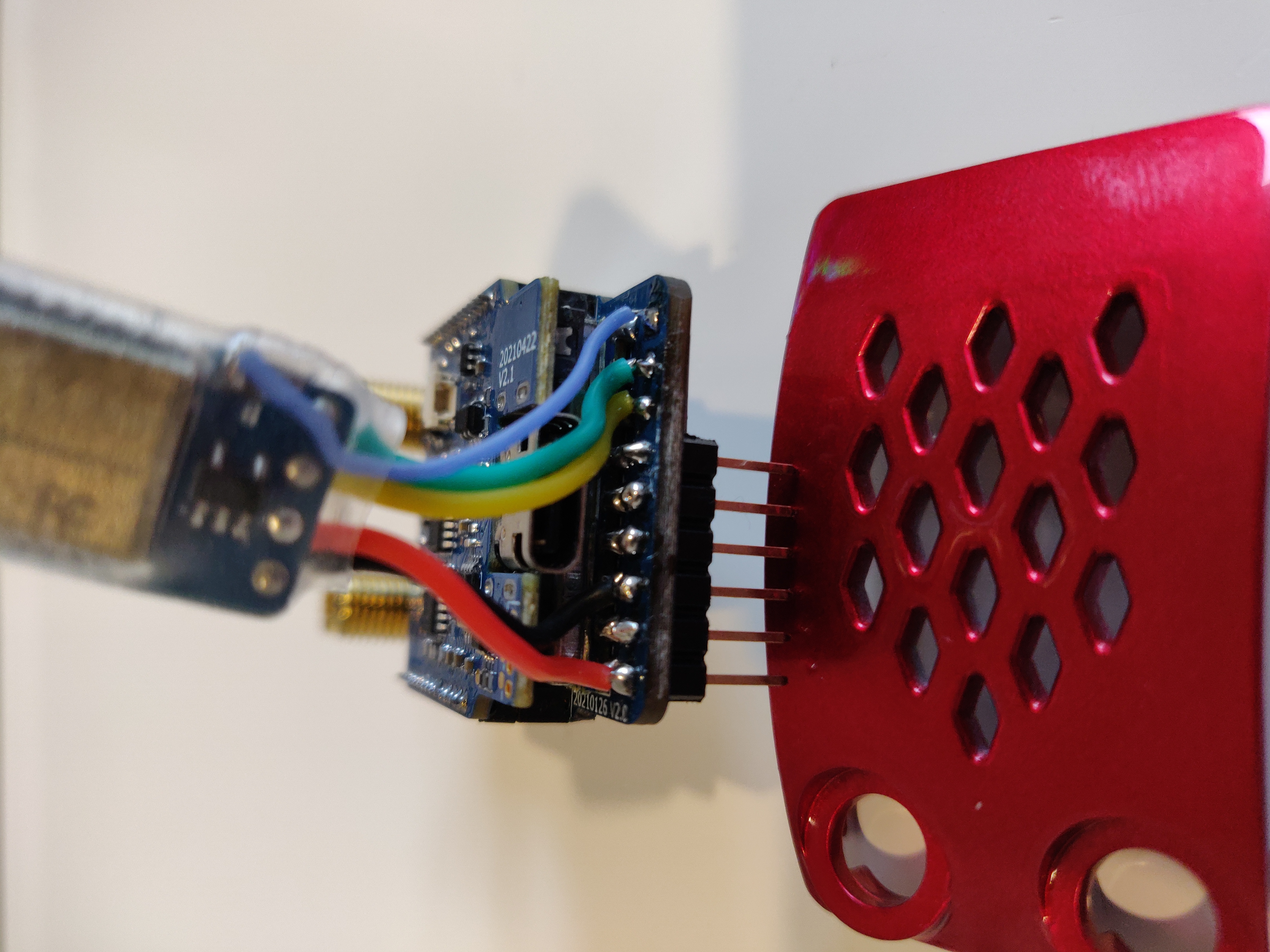
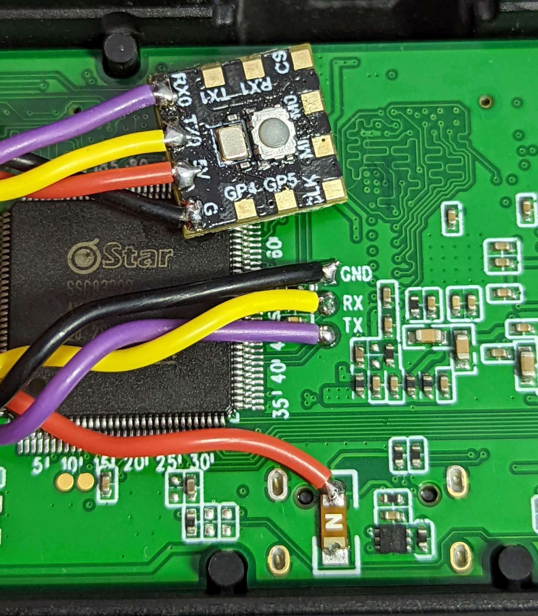
Shark Byte RX5.1 HDZero Module Connection
The VRX has an easily accessible UART on the main board, which is accessed by removing the 4 screws which secure the back plate. Use the goggle mount to pull the back plate from the housing.
Solder your VRX backpack as shown below:
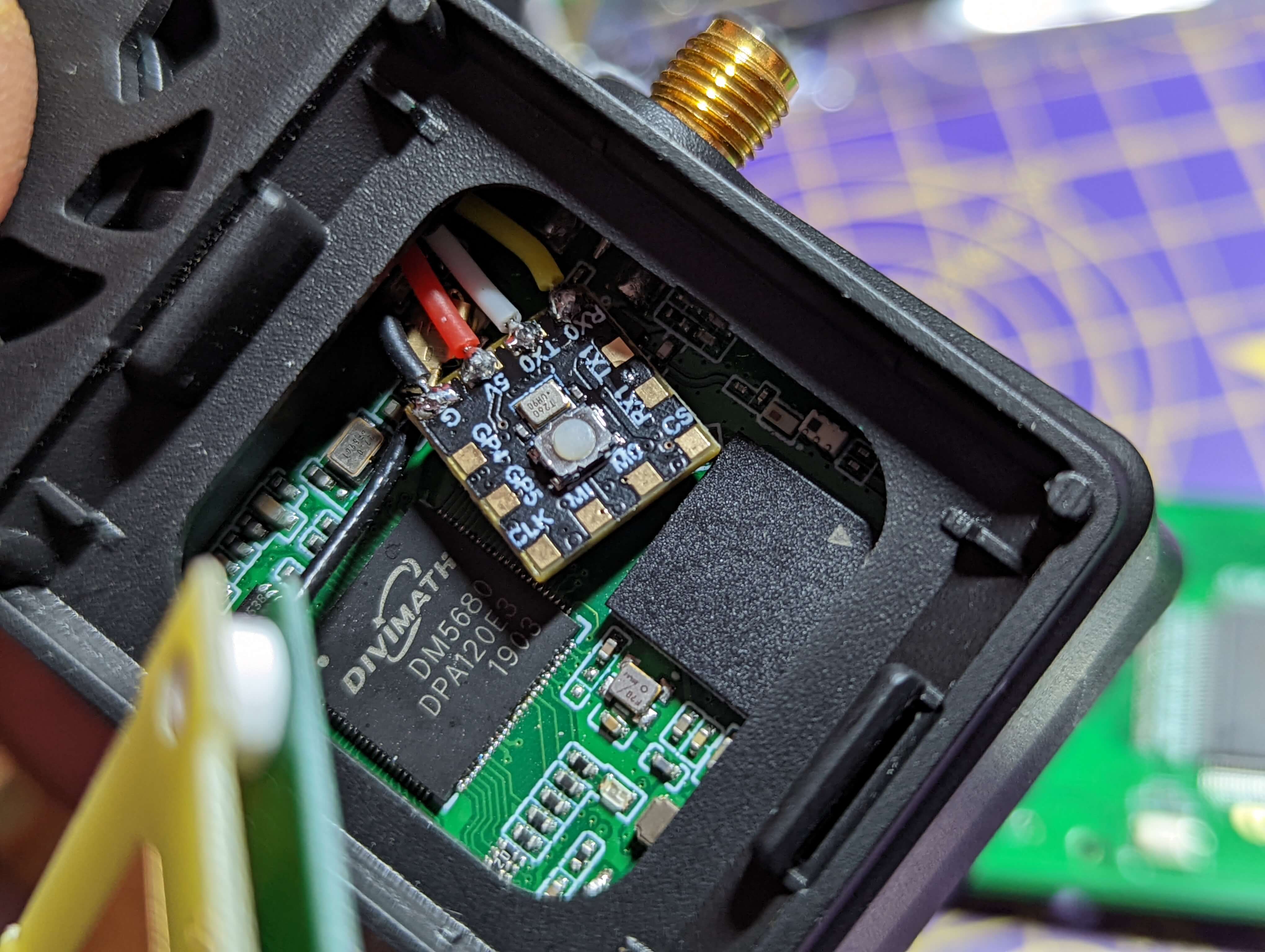
It is unlikely that you can close the back plate with the backpack module between the plate and the main board. There are two solutions:
- Route the wires out of the cooling vents and mount them externally
- Mount the backpack in the front patch, routing the wires through the goggle mount as shown below:
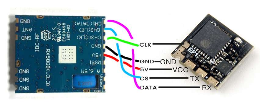
Generic RX5808 Connection
Make sure that your RX5808 is running in SPI mode. Then wire it up as shown below:
How to check you have updated the VRX Backpack Firmware?
Navigate to the WiFi Connectivity folder of the ExpressLRS v3 Lua script and select Enable VRX WiFi. The LED will begin blinking rapidly. Scan for Access Points and ExpressLRS VRX Backpack should appear. Connect to it and point your browser to http://10.0.0.1/.
If you have set your Home Network SSID and Password, point your browser to http://elrs_vrx.local/.
The main banner will show you what kind of device it is and the firmware version that's flashed into it.
Setup your TX Backpack
Proceed to the TX Backpack Setup section to setup your TX Backpack.
Operation
The Backpack Usage section provides further details on ExpressLRS Backpack Operation, including Binding, LED Status codes, and more.