Siyi FM30

Attention
ExpressLRS 4.x no longer supports STM32-based hardware. This includes the Happymodel PP, ES915 Tx and Rx, early NamimnoRC Flash and Voyager, FrSky R9, SIYI and ImmersionRC hardware.
The STM32 platform's limited compute resources and feature gaps (WiFi, Bluetooth, Backpacks) made for an inferior version of ExpressLRS that necessitated disproportionate maintenance burden for the Dev Team.
FM30
Flashing via STLink
- Target:
FM30_TX_via_STLINK
Note
The only way to flash the FM30 series is using STLINK. Luckily, their pads are pretty generous on the TX and easy to connect. This is a one-way process, there is no returning to the stock firmware after flashing.
- The TX module is opened by removing the four screws on the corners of the case using a small phillips screwdriver, then two further screws to remove the circuit board once inside.
- Connect wires to SWDIO, SWCLK, NRST, and GND to the header points shown in red above on the TX. Attach 5V to the VCC pad, not the 3.3V pad!
- Connect the other side to a STLINK programmer
- Flash using the
FM30_TX_via_STLINKtarget - After the flashing procedure, it is safe to leave the STLINK device connected to test that the firmware is operational, but unplug the USB connection before inserting the module into your handset for testing.
- Be sure your handset has the External Module type set to CRSF. See the general Troubleshooting section for other ways to determine your module is flashed and ready for flying.
Updating via DFU
- Target:
FM30_TX_via_DFU
Updating the TX is a lot easier and can be done via DFU without needing a STLINK.
- Remove the module from your handset. ⚠️ DO NOT plug in the USB while the module is still in the handset. There is no protection to prevent connecting the USB's power directly to your handset.
- Hold the button labeled "Bind" on the FM30 TX. Plug in the USB. There should be an "ExpressLRS DFU bootloader" device in Windows Device Manager. If not, the STM32 DFU drivers may need to be installed.
- Flash using the
FM30_TX_via_DFUtarget - Note that the process always reports failure but this occurs after flashing, so check for the message "File downloaded successfully", not what follows it:
Download        [======================== ]  97%        46080 bytes
Download        [=========================] 100%        47340 bytes
Download done.
File downloaded successfully
Invalid DFU suffix signature
A valid DFU suffix will be required in a future dfu-util release!!!
Error during download get_status
*** [upload] Error 74
FR Mini RX as TX
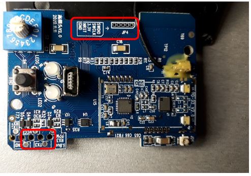
The RX has the same RF components as the TX does, making it a possible candidate for a small ~200mW TX module. Wiring to the JR Module Bay requires only 3 pins (JR pins are starting from the top down)
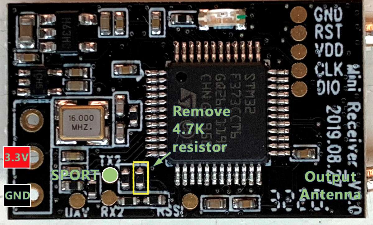
JR Module Pin | FR Mini Pin | Description |--|--|--| | CPPM | None | | | Heartbeat | None | | | VMain | VIN | Use the VIN pin on the pin header (middle pin), 3.3-3.4V. Do not connect directly to handset battery voltage-- this will burn out the 3.3V regulator even at 10mW output. Use either a 3.3V boost converter (to raise voltage from 1S provided by the handset) or 3.3V buck converter (to lower 2S or 3S handset voltage). The LDO has a very small dropout voltage, so there's not much benefit to bypassing this soldering directly to the VDD pad on the programming header. Expect over 250mA current draw in practice at 100mW. | | GND | GND | Use either the GND pin on the pin header (outermost pin) or the GND pad on the programming header. | SPORT | TX2 | Use the TX2 pad on the receiver and remove the 4.7K pull-up resistor. Without removing the resistor, the module will work okay-ish as a transmitter, but firmware updates through OpenTX will fail with NoSync
Flashing via STLink
- Target:
FM30_RX_MINI_AS_TX_via_STLINK
Note
The only way to flash the FR Mini is using STLINK. This is a one-way process, there is no returning to the stock firmware after flashing.
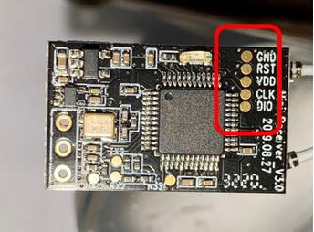
The flashing procedure is similar to the FM30 TX module flashing listed above but using these pads on the receiver. Use the FM30_RX_MINI_AS_TX_via_STLINK target for initial flashing.
Updating via UART
- Target:
FM30_RX_MINI_AS_TX_via_UART
Updates are done through OpenTX's built-in firmware flashing tool.
- Build the firmware using Configurator and selecting the
FM30_RX_MINI_AS_TX_via_UARTtarget. The build process will generate afirmware.elrsfile. - Copy this file to the handset
FIRMWARE/directory on the SD card. - Flash the firmware to the module using OpenTX
- Hold the MENU/SYS button on the handset to open the system menu
- Press PAGE to navigate to the SD card browser
- Scroll down to the FIRMWARE directory, and press ENTER
- Find
firmware.elrsand long press the ENTER key to open the context menu - Select
Flash Ext. ELRSfrom the menu
Troubleshooting Flashing
Unable to connect to the target device
Unable to connect to the target device (click/tap to expand)
If the flash fails with "Unable to connect to target device" (not "No STLINK found!") it is likely your STLINK clone does not have the RST line connected, but you can trigger the needed reset manually with a little more effort. The reason this is needed is that SIYI has disabled "Software Reset" to protect you from stealing their firmware binary.
- Verify your wiring
- Make sure the TX board is powering up (the LEDs light up)
- Use the STM32CubeProgrammer or STLINK GUI to connect see next step.
- Before you press CONNECT. Short the RST line from the TX to GND. Press CONNECT and quickly remove the wire from the GND pad.
- If it works, the GUI will tell you that the board is readout protected and must be disabled. Do this.
Flash loader run error
Flash loader run error (click/tap to expand)
Before both the TX and RX can be flashed using the st-flash utility used by PlatformIO on Linux, the STM32 chip must have its "Readout Protection" (RDP) disabled, which was set by SIYI at the factory to make our lives more difficult. The windows flashing utility usually automatically disables this, but the Linux utility does not. If you do not disable readout protection you'll get this cryptic error when flashing:
2021-07-06T21:08:42 ERROR flash_loader.c: flash loader run error
2021-07-06T21:08:42 ERROR common.c: stlink_flash_loader_run(0x8000000) failed! == -1
stlink_fwrite_flash() == -1
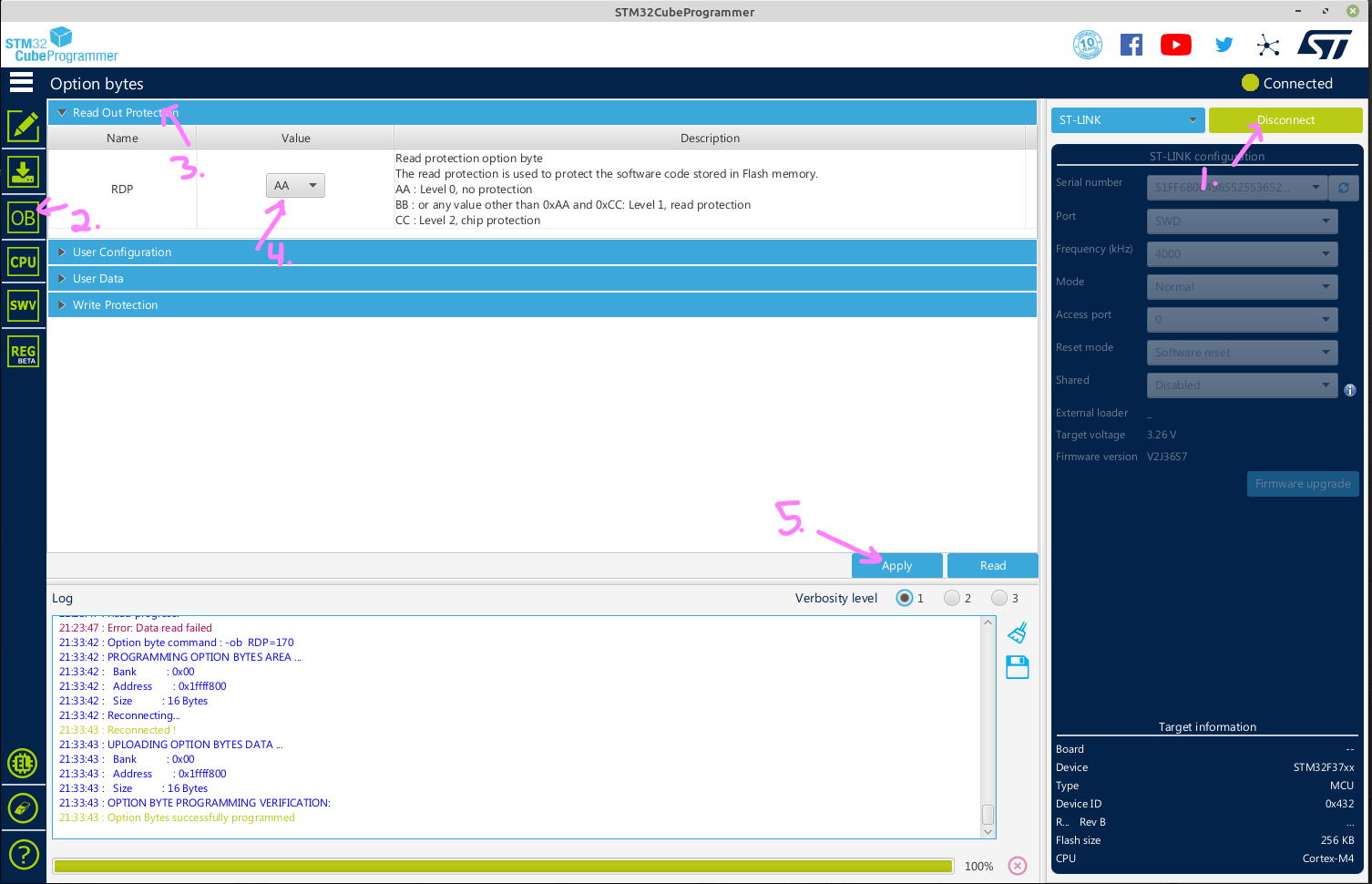
- Click the "Connect" button to connect to the ST-LINK device. You'll probably get a popup error Error: Data read failed. That's normal. If it says it can't connect or no device is present, you'll have to figure that out first.
- Click the "OB" button on the left.
- Expand the "Read Out Protection" section.
- Select RDP = "AA"
- Click the "Apply" button at the bottom.
- You should get a message indicating the "Option bytes successfully programmed". If so you're good to go. Click "Disconnect" at the top and flash from PlatformIO now. You can also flash directly from this GUI if you have the binaries and know their target addresses.